
Splines are fine for the Gokstad Viking ship
Part 5
1. In the name of accuracy, here is a kind of invisible detail of the mastfish. If you want to go that far, you will have to Boolean a box out of the mastfish to end up with this slot. The mast would be slipped into this slot and then locked down by the mastlock. Essentially, a large block of wood that was on one end shaped like the mast and once inserted held the mast securely.

2. I expect the back side of the mastlock to be somewhat slanted, so that gravity
would drop it down against the mast contour. It's an ingenious device.
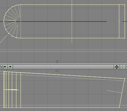
3. Next, put a lid on it. Create a box with these
numbers:

4. Rotate it, or pull the points until it is
slightly above the mastfish, and parallel to its top surface. Then pull the
back point to get a siluette as you see here.

5. Unless you have KW Edge Smoother by now, select
the two mastlock (oh, yes, before I forget, name the box: "Mastlock")
top polygons and bevel them. Just for grins I beveled the bottom polygons as
well, giving them the same treatment as the top (including the gap elimination
and point merge as described below).


6. To eliminate the unsightly gash, in the sideview,
pull the points on top of each other and do a fixed point merge with 10 mm selected.
Two points delete and you are ready for the next step.


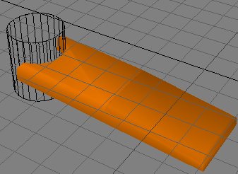
7. Notice the now smoothly connected polygons. Bring the old mast stump back
into play, and take a Boolean bit out of the lid. Which leaves you with three
options.
1. Live with the stress line. 2. Select and cut and paste the affected polygon, or 3. cut and triple it as you did before with the oar-ports. Your call.
Since the item is very small, I decided to just cut and paste the poly. Stress lines relieved. Save your file as ship_tute15.lwo

8. The next item should be the T-shaped yard supports. They were removable as
well, as least the rear one, to facilitate lowering the mast, after which time
it could be set up again as added support for the yard-arm. It is suspected
that even the mast might have been lowered upon the yard-arm supports, (maybe
that's why there are three of them) to provide added deck space during the hectic
disembarcation and boarding phases of the raid. Obviously, the most complex
part is the top crossbar. On the 50 mm grid, lay down these points.

9. Select the points as shown and connect them with an Open Curve. Then
select the bottom twp points, and connect them with an Open Curve.

10. Center the points in X.
11. Select all of the points sequentially, and hit <p>. you will have
a polygon.

12. Select that polygon, hit <E> or CONSTRUCT/Extrude and give the thing
some depth.

13. Notice those straight lines? There will be lots of them. Delete them all.
In some cases you will have to go to high magnification to differentiate them.

14. In one case, unable to separate them out, I sacrificed a short poly to get
rid of the large one.

15. It was easy enough to restore. When you're all finished, flip the polys
and then, once more, in sequence, select all of the points, UNSELECT ONE ROW
OF THEM, and hit <p>.


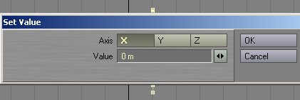
16. Copy, cut and paste that new polygon to an empty layer and slide it (or
use Set Value) to X = zero and paste it back into the object layer. Automerge
all points. And there is the completed yard-arm support crossbar.

17. On the 500 mm grid, slide it to about here and then give it a post to rest
on. Create a box like this:

18. Now, in the sideview widen the crossbar just a little, to have it extend
more over the edge of the post. This one, as you can see here, is sitting right
in front of the mast.

19. Cut and paste the crossbar into the same layer as the support post, select
all of the polygons, hit <q> and name the combination
"Yard Support". Then copy and slide them (shown in the 1 m grid) about
7 m one way, and mirror the yard support across to the other side, for a total
of three of them.

20. Now they all need some feet. Close in on the right one and go into an empty
layer, keeping it in the background. Create a box with these values.

21. Next reshape it in profile like shown in the left image and from the top
as shown in the right image.


22. Now select it, name it (yard support base), color it, and mirror it. This leaves us with two of them on solid footing. One remains.

23. This is the one sitting across the mastfish. Zero in on that one, and keep
it in the background layer and place the following points as shown, in the 200
mm grid.

24. Now repeat the whole process we went through with the crossbar: 1. Select
and connect the points on the curvy side with an Open Curve. 2. Select the points
adjacent to the straight edges and connect them with an Open Curve, one at a
time. 3. Select all the points in sequence and create a polygon. 4. Select the
polygon and extrude it. 5. Delete the straight edges. 6. Reselect the remaining
points sequentially and create the final smooth polygon. you will be left with
something like this.
Next delete the current central support strut.


25. Now to do it all over again to create these points:

26. Select them in sequence and hit <p>. Next extrude
('e') the new polygon, as shown, and flip the polys, and cut
and past it all into the layer of the previous part.

27. Now select all, name it Ctr support base, and color it back in.

29. When you select all of the relevant layers, this is what youll see. Save your file as ship_tute15.lwo
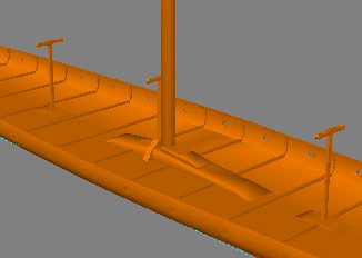
A rendering shows us where we are, thus far. BTW, the file includes the bucket. There were several on each Viking vessel, and just consider it a freebie. If you can't create a bucket by now, I would not know how you got this far.

You can download the .LWO file here: Viking5.zip
On to part 6 of this growing exercise. In Part 6 you'll create the sea chests (rowing benches), the rudder, the oars, the yard.
Created by Karl Stocker (pixeltek), a 3D hobbyist and occasional freelance artist. If you'd like to contact him, send email to: pixeltek@yahoo.com or visit his website at: www.cosmic-pearl.com