
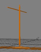
Splines are fine for the Gokstad Viking ship
The Gokstad rudder and pivot.
This whole thing is evolving essentially as I build it. Being a novice myself, many of you may already have knowledge that will let you execute much of what I do in simpler or maybe better ways. However, for those at my own or lesser skill level, this is a fair way to put this thing together. As you can tell from the photos, we are staying very close to a historically accurate model.
1. First the yard. Big deal. It's a stick. Create a disk (rod) as shown, and bevel one end. Then mirror it and you've got the yard.


2. Next I discovered that we needed to do something that is not a big deal,
but kind of important to make things look right. Select the Mast, Mastlocktop,
and Mastfish. Hit <h> (MODIFY/Size) and and we will change
the size of those things to be a little more in line with historical drawings
and my photos. Go to the 500 mm grid, and looking down, reduce the size to the
smaller dimensions shown. Reasonably close is quite sufficient. After you are
finished, you will notice that the objects shrank in every axis, meaning that
you will have to drop the unit back onto the deck level.


3. Place the yard in front
of the mast (big surprise, that one ;-)). Save file as ship_tute16.lwo
4. Now on to the rudder. The rudder is a fairly
complex item and this is probably where the experts among you will have many
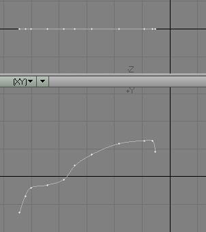
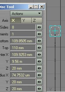
different ways of building it. First the rudder hub. That one's easy. I just
made a little open curve from a few points and lathed it. In the 50 mm grid
it looked like this. Oh, hit F2 to get it centered around the
X,Y axes. It's easier that way. We'll maneuver the final product to wherever
it needs to be later. When you have the points and connected them with an open
curve, lathe! Go to MULTIPLY/Lathe, and as soon as you hit the <n>
key for the numeric panel, you will see this, provided you are set up with a
360 deg End Angle. If not, change to 360 deg. Select the item, call it Rudder
Hub1, and use the preset METALS/Iron, to color it.

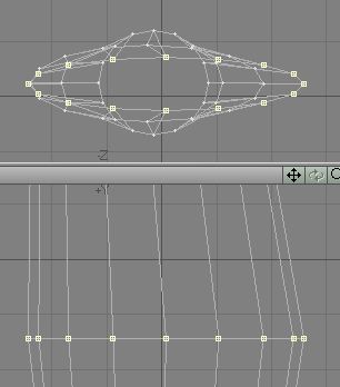
5. Move the hub to X = 15.95, Y = -810
mm, Z = 1.65 and that will get you close to where you need to be. Next
you will have to rotate it. What you need to do is to have it located on the
outside of the hull on the right (Starboard, see how old those terms are!) side
to be able to attach the rudder there. Use the Rudder Hub layer and the ship
hull layer and switch between them until you have achieved the proper relationship
between those two parts, as shown in the right image.


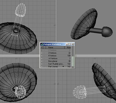
6. There is another little
piece to this thing. An axle sort of device that seems to be able to pivot,
as well as lock the rudder in place. Go to an empty layer and keep the Rudder
Hub layer in the background. Create a small disk and stretch it. Attach a squashed
ball to the end and that's it. While pretty close to the pictures, I completely
winged it. It will be nearly invisible and, as is, very closely resembles the
real thing. I am working off drawings as well as pictures. Since each ship was
unique, so was the rudder design and embellishment. Name the item Rudder Pivot.
I think that would be accurate. You may even want to add the tie-down strap.
I did not (yet). The location and purpose seems to be slightly at odds between
resources. The pivot essentially sticks straight out to compensate for the curvature
of the hull and allow the rudder freedom of movement. You can see that I tilted
mine ever so slightly, though that might not be necessary (as the photo of the
rudder reconstruction shows). Combine the Rudder Hub, the Rudder Pivot, and
paste them into the ship hull layer.

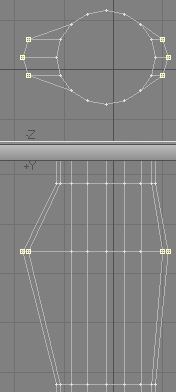
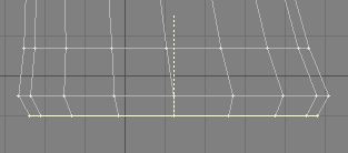
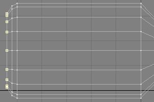
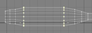
7. Now to the rudder itself. Fun is guaranteed for all. I started with a straight,
sectioned rod. Why so many sections? Because I think there'll be lots of shaping
along the way. On the 500 mm grid, slide the sections as shown in the second
image. Go to the point editing mode and move the points of the 3rd tier down
as indicated. After selecting that row of points, go to the top view and deselect
all but the six points shown. Hit the <h> key and center
the tool symbol somewhat toward the right and do a horizontal stretch. You see,
you are beginning to start the shape of the blade here.


8. In this vein, you will continue down the rod. Here's are next rows of points.

9...and the next rows...

10....and the bottom two rows.


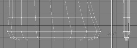
11. When all is done, you've got this nice little rudder shape. Bevel the top
polygon as shown, and then...


12. fix up a few points to make the vertical lines a little smoother.


13. Now cut, or bandsaw (I used CONSTRUCT/knife) the bottom row of polys to
allow you to add a little curve in there, as I did..


14. Finally, select the bottom polygon, flip it <f>,
and MUTIPLY/Smooth Shift it, twice. Take each of the new point rows and use
<h> to push them inward a little. Nobody says you can't
use <t> to slide things as you need them. Make sure the
reduction is done in both views. Flip all polys as necessary.
15. Now, if you so desire, shape the bottom of the rudder round, as I did. Not
a big deal. All rudders were slightly different, as you by now have been made
aware of by me. What you end up with is this nice little Viking ship rudder
shape. Pat yourself on the back. Uh, if you haven't yet, name it "Rudder".


16. The Rudder Control Arm is next. It's waaay simpler than the rudder. First
create a disc.and extend it. slide the segments as shown.


17. Now use MODIFY/Stretch or <h> to reshape the first
segment as shown here. The Rudder is in the background layer, in case you wondered.
Then, after extending the handle end slightly beyond the diameter of the Rudder
(background layer), bevel the end polygon twice.
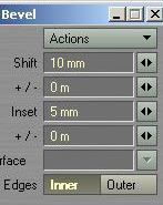

18. No go to the other end of the control arm and bevel that polygon three times
<b>, <n>:.
a) Shift 20 mm - Inset -25 mm
b) Shift 100 mm - Inset 0
c) Shift 20 mm - Inset 20 mm
19. Go to the front of the control arm and copy and paste the polygons as shown,
into an empty layer. You'll use that as a Boolean object. The composite image
shows the polygons involved and the result after the Boolena subtraction. The
Rudder top now has a proper slot in it.

20. Neat little rudder, is it? Now all you have left to do is to "pin the
tail on the donkey". That is get the rudder handle combination mounted
on the pivot. After all of this work, save file as ship_tute17.lwo


21. Guess what will become an oar? How about the rudder control arm? Works for
me. Select it, make a copy of it and paste it into an empty layer. Select the
point of the knob at the end and with <t> move them toward
the right, as show. The grid is at 500 mm.

22. Shaping the blade of the oar. Take the point on the leading edge of the arm and slide them as shown. Follow suit with the rest of them until they are in place. The second screen-grab is on a 100 mm grid. You can easily see where this is all going to end up. A few cuts (blue line for the initial one) will soften the curve.

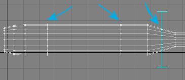
23. All the cuts are in place and you can shape the oar a little more. Blue
arrows indicate the cuts.
24. Grab the two rows of points in the middle and use <h>
to stretch them vertically...and the right image shows you what you want to
achieve.

25. Now sqeeze the blade a little, use <h>, and you will
be left with a very passable oar.


26. On to the Rowing benches/ sea-chests. With storage space at a minimum on
those vessels, they used sea-chests as rowing benches. Very practical. They
were found with curved and flat tops. All heavily banded with iron straps. Make
a disc and delete the lower half of the points. Follow with a box and you've
got the sea-chest nearly finished. They mounted them on legs, I guess to keep
the contents dry. Two more little boxes (one copied and slid) take care of that.


27.Now for the iron banding. Copy the sea chest to an empty layer. Take the
knife and cut a slice out of the middle somewhere. Hit <h>
(MODIFY/Size) and enlarge the slice slightly. It's your iron band. Delete the
rest of the chest. Copy a few and spread them across the chest. Then select
them, name them straps, and copy them to the chest. Use the same color you used
for the rudder pivot and hub, to color the bands. I made them just a little
more shiny.


29. And voila, one burly seachest. Now you realize, that at some point you will have to make 32 chest and at least 30 oars and distribute them evenly around the ship. I'll give you some pointers. Of course, setting up one quarter of the ship and mirroring the rest will pretty much take care of it, with some adjustments. On the 200 mm grid, stretch <h> the seachest to these dimensions. When you move the cests around, make sure none poke through the hull.


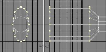
30. What remains is the sail. The sail will be fastened to the yard with hoops of rope. So, go forth and make some hoops. This is what we need. Open an empty layer with the yard in the background and create these points. Connect them with a Closed Curve.


31. Go to an empty layer with the curve in the background and create a small disk in the Front/Rear view.

32. Swap <'> layers and go to MULTIPLY/Rail Extrude, set it to Uniform Knots = 20, and hit "OK". Name the result "Hoop".


33. Go forth and select, copy, and slide, until you have six of them, as shown on the left. Then mirror the bunch in the Z axis. Save file as ship_tute18.lwo


You can download the .LWO file here: Viking6.zip
Part 7 will be the sail and rigging.
Created by Karl Stocker (pixeltek), a 3D hobbyist and occasional freelance artist. If you'd like to contact him, send email to: pixeltek@yahoo.com or visit his website at: www.cosmic-pearl.com