
Splines are fine for the Gokstad Viking ship
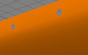
Inside view of the Gokstad ship (looking aft). You can see the Mastfish and the central yard support and get a clear view of the hull and deck.
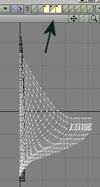
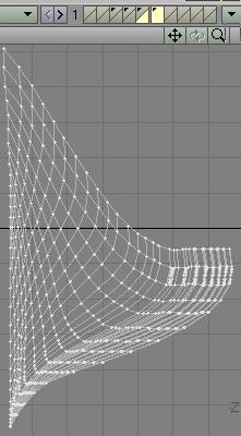
1. So, still here, eh? I'm glad. I won't feel so alone in my effort. Once we get to the deck and topside details, So, let's open the file ship_tute7.lwo, and select layer 3 and 5 and keep layer 4 in the background. To select multiple layers, depress <Shift> while clicking on any layer, same as if you're slecting multiple points or polygons. The image shows you what you want to see.
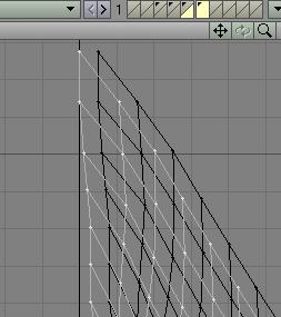
2. While holding down the <Ctrl> key, with <t>
selected, slide the hull sections to the right, as you see here. Leave no gap
between heel and hull.

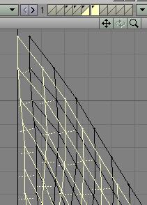
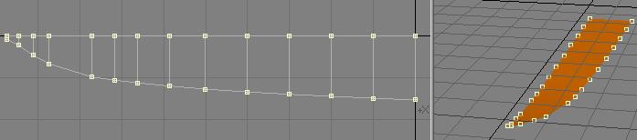
3. However, there will be a gap at the top. To eliminate it, select the points shown and go to MULTIPLY/Drag and slide each one carefull to the left. I then followed through by sliding a couple of adjacent points over a bit as well, to keep the lines smoothly curved.


4. Here's what we've got now.
5. Now select layer 5.
What we will do next is to reduce the sizes of the polygons that have oar holes
in them. Go to CONSTRUCT/Knife (Shift-k) and cut like so:

6. When you hit the spacebar,
the knife will be deselected and you will have a cut down the hull.

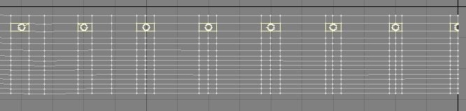
7. Repeat this process next to each oar port and end up with this. Now select
each polygon that contains an oar port.
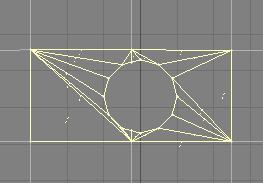
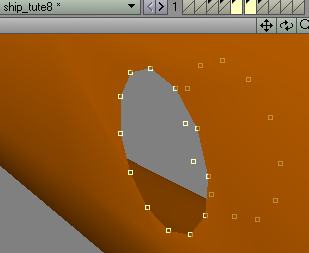
8. Go to CONSTRUCT and click on Triple and the result, magnified to show the
detail on one of the oar ports is here:
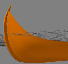
9. Looks like it was well worth the effort. I am pleased with
this. We're all learning here. Definitely I. Save your file as ship_tute8.lwo
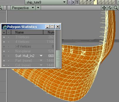
10. Next, we need to give the hull some depth. Remain
in layer 5 and in the polygon edit mode select all polygons (use the polygon
statistics window)

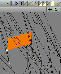
11. Hit <c> select a new layer (6), and switch layers
<'>. In the new layer hit <v>
and the hull section appears.
12. Hit <t> and while holding down the <Ctrl> key, slide the hull section to the left. You can now see the original hull in the background layer.
13. Select all the polygons in this layer and flip them. You now have an in-facing
and an out-facing hull section.
14. Next you must creat the top rail of the hull. In the side view, with BOTH
hull layers (in this case layers 5 & 6) selected, in the point edit mode
select all the points along the upper edge. Hit <c> and
go to layer 7 (as shown on the illustration) and hit <v>.
You now have copied and pasted all of the points from both hull sections to
layer 7.

15...and here they are.

16. In layer 7, select points, in sets of 4, sequentially and hit <p> to create a polygon. Do that for all of the segments. You'll end up working in different view ports for convenience.


17. When you're all finished, go to the polygon edit mode. Flip <f> any polygon that is not facing up, and then select all of them. Hit <q> and in the Change Surface box name them Rail2. Hit ok, and it will turn grey.

18. In the Suface Editor you now see "Rail2". Go to "Default", where our original color choice is located, right-click and a tiny window will pop up that reads "copy" and "paste". Click on copy and then go to "Rail2". Right-click and in the tiny window click on "paste". You color will now be assigned to "Rail2". Neat, eh?
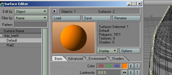
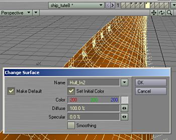
19.Go to layer 6 and name the in-facing hull with oar-ports: "Hull_In2". Then same procedure as above.
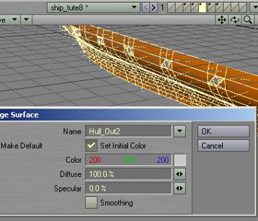
20. Go to layer 5 and name the out-facing hull with oar-ports: "Hull_Out2". Then same procedure as above. Cut and paste the contents of layers 6 & 7 into layer 5.
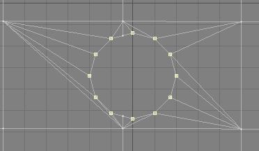
21. Now to a real pain in the butt. In the combined layer 5, select every point as I show in the illustration. As you probably noticed already, I neglected to pick the intermediate points that appear in two of the edge segments for a reason. Firstly, I have no intention to affix the oar-port liners to the hull, to not cause new stress areas. Secondly, I intend to only create half of each liner and then mirror it. Now, that's just a suggestion. Read on and you may decide to rather connect all of the points with polygons, one at a tine. That way no final adjustment of the mirrored portion is necessary. Your call.
22. After you have selected all the points around each port, copy and paste them to layer 8. Switch layer and now in layer 8 start to create polygons.
23. As you can see, I did only 1/2 of each hole.

24. Then I select those polygons, ONE HOLE AT A TIME, and mirror each one (hit <Shift-v> or go to MULTIPLY/Mirror). The drawback of this is that you will have to correct the point locations. Select the affected points and drag them to where they should be.


25. A big job, I know. After you are finished, do a FIXED point merge with a 30 mm distance, and then, in the polygon edit mode, select all of the polygons and name them "oar_ports"..

26. Cut and paste the hole liners into layer five, and this is what you have. Save your file as ship_tute9.lwo

27. Now for the deck. Go to layer 5. You'll have to back-paddle a bit here, for convenience. Go to the Polygon Stat window and slide down to Surf: none. Click and hold on the down-facing triangle and select surface Hull_In2. Copy and paste it to layer 6.
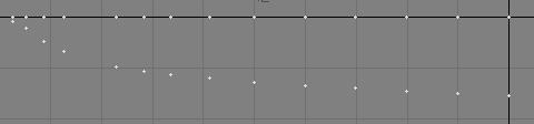
28. Now, in layer 6, in the side view carefully select these points. Copy them to layer 7.

29. Switch back to layer 6 and delete what's in there. Switch back to layer 7 and copy and paste the points to the empty layer 6. Back in layer 6, in the top view, you have one set of points, and you know there is an identical set in layer 7. Select all of the points in layer six and hit <v> (Set Value). The Set Value window pops up. Change the axis to Z (in my case, and I hope in yours as well) and click "ok".

30. All the selected point zip up to the Z = 0 line.

31. Cut <Ctrl-x> and paste the points into layer 7 and delete the ones that are too close together, as I have.
32. And now it's back to routine. Select the points in sets of four, sequentially, and hit <p>. If any polygons face down, flip the up. Go to the Polygon Edit mode and select all polygons and name them "Deck2". Then follow-through with the Surface editor, and change their color back to that of Default. Next, cut and paste the deck into layer 5.
33. In layer 5 you will now have a double-sided hull, with oarports and a deck surface. Save your file as ship_tute9.lwo

At this point it remains your option to duplicate all of the steps necessary to create an inner and outer hull as well as a top rail surface for the hull section without oar ports. I will only work on the hull with oar ports from here on.
You can download the .LWO file here: Viking3.zip
On to part 4 of this little exercise.
Created by Karl Stocker (pixeltek), a 3D hobbyist and occasional freelance artist. If you'd like to contact him, send email to: pixeltek@yahoo.com or visit his website at: www.cosmic-pearl.com