
Splines are fine for the Gokstad Viking ship
1. The worst is behind us, I think. It's time to put some of the pieces together. Again, I will concentrate on the hull with oar-ports. Open ship_tute9.lwo. There is one more thing that can be done while working with a quarter ship: ribs. Go to the Polygon Statistc window and use the Surf: function to select the Hull_In2 and Deck2.

2. Copy and paste them to layer 6. Just had a thought - it happens. Go to layer
6 and select Deck2 and cut it <x> and then paste it into layer 7. Then
select layers 6 & 7 together.

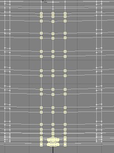
3. In the side and top view, just like when we
made the cuts in Part 3, you will now cut the hull and deck into thin strips.
Go to CONSTRUCT/Knife and cut where I show you. Don't worry about them being
exactly even or in the exact place where mine are. Just get reasonably close.
I highlighted the cuts.

4. Now delete everything that is not a cut, and
you'll be left with something like this:

5. In the sideview select the points and slide
them such that all slices are about the same width. Then go to layer 7, what
was the copy of Deck2. Select all of the slices and go to MULTIPLY/Extrude and
pull them up a little and there are your deck ribs. Select all of the polygons,
magnify to see if they need to be flipped. Mine did.

6. In Layer 5 do the same, but extrude toward
the inside of the hull section, since the ribs that are visible above the deck
will be near vertical. Extrude horizontally and flip polys if necessary.

7. Paste them into a single layer and name them Ribs. Go to the surface Editor
and copy and paste the default color, but reduce the smoothing to 30 degrees.
Cut and paste the ribs into layer 5. Here's what you should have:

8. After selecting layer 4 & 5 and mirroring the content, I just about pulled
the plug on this project. Subsequently, I spent a lot of time tugging the points
at the merging edge, until the hull looked smooth. You are welcome to play with
this, but, if all else fails, you can of course download the .lwo file, which
I painstakingly corrected to the best of my limited ability. you can readily
see where the center is not integrating very smoothly.

9. Save your file as ship_tute10.lwo, go to the Point Edit mode and select
these points. The objective is to get a smooth transition established. After
that, attack the oar-ports. I found this task to be the toughest so far. Have
fun.
10. Now the oar ports. You can see the before and after, here:


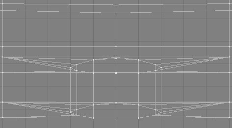
11. On second thought, I think we want to flatten the whole midsection in a
little. Select these points and then with <t>, while
holding down <Ctrl>, give it all a little push to the
top of the screen.

12. There, this is way, way better. Now I'm getting happy again.


13. After all is said and done, and you've sweated appropriately over your creation,
you should have a reasonably smooth joint and are ready to mirror everything
in the necessary axis (Z in my case). What we have is one nice
looking Gokstad Viking vessel. Whew! Save your file as ship_tute13.lwo

14. Looking at the photo at the top of the page, I see that a small cover is
applied over the upper part of the ends. To do something similar (keep in mind,
as I already said before, each Viking vessel was a one-off construct and uniquely
built by one shipwright to the specifications of the local Viking land owner,
who had the wherewithal to afford a raiding or trading vessel. So barring some
real weird stuff, we are never wrong.). Select the points as I showed in the
end-on view. When you do that, and hit <p> to create
your polygon, you will immediate discover that you are also selecting the points
on the opposite end of the ship. Set your views up as I did, then delete the
opposite number. Also, you may want to do a point-merge (<m>)
first on those points you intend to connect with a polygon. I found that to
be very helpful. I named the polys "endcap". For efficiency sake,
select the points twice and delete one side, make your poly, select them again,
delete the other side, and make the second poly on the opposite end of the ship,
and so on. I will go only four polys down.


15. Just to make it a little nicer, let's give the endcap a little edge. Points
are already on hand. Use the inner hull points, as shown, for this:

16. Looks ok, doesn't it?

17. Alright, now for the very unique Viking "mast-fish" with its locking
block. It's a device that one of those bright guys had come up with, that allowed
them to quickly drop or raise the mast. It was reputed to have been so strong,
that it could hold the mast without any rigging. However, most old drawings
and carvings do show rigging, nonetheless. The reason they needed to drop or
raise the mast quickly was strictly for tactical advantage. Their lightning
attacks required a maximum of maneuverability. So, for that reason, whenever
they approached their point of attack, so to speak, they would drop the yard
and mast, and start rowing. With 30 oars, the light and shallow drafting vessel
was very rapidly maneuvered, slammed into the beach and minutes later, the raid
was on. Any enemy vessels would depend solely on wind and sail, and the quickly
rowed Viking ship could outmaneuver them to keep out of range of arrows and
spears. Over half a millennium later, the Venetian fleet and similar Mediterranean
warships were once more rowed, carrying a single huge, long-range, and powerful
cannon in front, giving them a distinct advantage over the large French and
English sailing ships, that had to depend on the wind to bring their broadsides
to bear.
Go to an empty layer and create a box with these specifications.

18. Now modify the box in this way. Use point edit and select the section divisions
and slide then as shown <t> (while holding down <Ctrl>).


19. If you want to bevel the edges of this box, a great little plug-in will
be of enormous help. The KW
Edge Smoother is shareware and can be downloaded from here, and a single
application to the object resulted in this. Even if you don't want to purchase
it, have a look at the site anyway. Big difference, isn't it? This was done
with the default 50 cm bevel. I love that little plug-in.


20. It is already properly located in the X and Z axes, and only needs to be
slightly moved in Y until it (BTW, name it "Mastfish") is just barely
embedded in the deck surface. You can just see where the ribs, that run across
the deck intersect the Mastfish.

21. Next you will have to cut a hole into the mastfish. Create a disk with these numbers and in the indicated location:

22. Put the object into the background layer and do a Boolean subtraction. This results in an unsightly stress line.


23. Even I, ever so slowly, learn a lot doing this project, and we know how to fix those stress lines now. One way is to just hit <Tab> and the subdivision will eliminate the stress line. Try it. The other way is to cut the Mastfish, which immediately releaves the stress line. Either live with that, or continue. For even greater stress relief select that small polygon around the mast hole and go to CONSTRUCT/Triple. Triple, as you can see, goes a long way to minimize any stress problems. Save your file as ship_tute13.lwo


24. I just noticed that I already had included the mast in the downloadable file. Ok. No problemo. If you still want to do the mast, do this. Go to layer 6 where the "stump" we used to do the Boolean subtraction, is located and place the mast in layer 8 in the background. Select the bottom points of the stump and pull them down some. Then pull the top points up until the mast narrows.

25. Where the mast narrows, use the stretch tool, and reduce the diameter to 80% of the bottom dimension. Next, do three extrusions, to taper the mast as shown.

26. There is one more thing that is NOT in the downloadable file. I decided, since the mast will be laying down, when the ship is rigged for attack or landing, to bevel the bottom. BTW. Speaking of laying the mast down. The masts would weigh as much as 800 pounds and were short enough to fit on the deck in the back half of the ship. That way the Vikings could quickly slide it into the mastfish and set it up. So, don't stretch the mast beyond of what I gave you in the file. This is an automatic size limitation.

Here's what we've got thus far: We may be able to eliminate the slight pulls up front, and don't forget, horizontal boards are what is making up the hull. Once textured, that should be all but invisible. Also, as I keep telling, each Viking ship is pretty much unique, you can extend the keel and shape it into anything. A spiral was common, as on the Oseberg ship, as were figure heads. I recall a ram's head from the movie, The 13th Warrior.

You can download the .LWO file here: Viking4.zip
On to part 5 of this growing little exercise.
Created by Karl Stocker (pixeltek), a 3D hobbyist and occasional freelance artist. If you'd like to contact him, send email to: pixeltek@yahoo.com or visit his website at: www.cosmic-pearl.com