
Part 8

The Star Wars X-Wing Fighter Project

This is what you will get out of the downloadable file. If you have gotten this far, adding the nurnie details will be tedious, but that's well within your skill level. I'm throwing in the pilot and most of the details, as well as a miniaturized version of my R2D2 astro droid. Since my texturing is pretty much based on procedurals, most of them are included. The rest are derivatives of what you see here. I know, I know, I am being waaay to generous again.
To place the fighter in the X-Wing configuration: 1. Mirror all of the parts of the Wing, the gun, and the engines in the Y-axis (vertical). 2. Cut and paste all of the parts of the new mirrored Wing, the gun, and the engines to a new object file. The Wing that you have from me is the Lower Left wing. The new mirrored wing then is the Upper Left wing. Name the File accordingly, e,g, Upper Left wing. It should contain all of the other parts too, engines, wingbox, pipes, gun, etc. In short, everything that you mirrored up. 3. Cut and paste all of the parts of the original Wing, gun, and engines to a new object file. Since that is the original Lower Left wing, name that new object file Lower Left wing. 4. Save the remaining old (now wingless) file, as fuselageX. Make sure you mirror the fuselage halves and the cockpit canopy halves too. 5. In the Lower Left wing file rotate the wing down, 17 degrees. Make sure that it pivots around the innermost corner, such that it won't extend into the Upper Left wing later. With that done, mirror the rotated wing across the X-axis. You now have two wings that are rotated down, on the opposite sides of the centerline, i.e. the Lower Left and Lower Right wings. Save your file. 6. In the Upper Left wing file rotate the wing UP, 17 degrees. Make sure that it pivots around the innermost corner, such that it won't extend into the Lower Left wing later. With that done, mirror the rotated wing across the X-axis. You now have two wings that are rotated UP, on the opposite sides of the centerline, i.e. the Upper Left and Upper Right wings. Save your file. 7. Go to the fuselage file. Find the wing locks/guides. Delete one of the sets. Then select the Upper guide, and rotate it UP 17 degrees. Next select the Lower guide, and rotate it DOWN 17 degrees. Now mirror the two rotated guides across the X-axis. Save your file. 8. Go to Layout. Load the fuselage object file, the interior (cockpit/pilot) object file, the R2 file, the LL wing file, and the UL wing file, and you will have an X-wing fighter in the attack formation. Save that scene, once you have your cameras and lighting set up. |
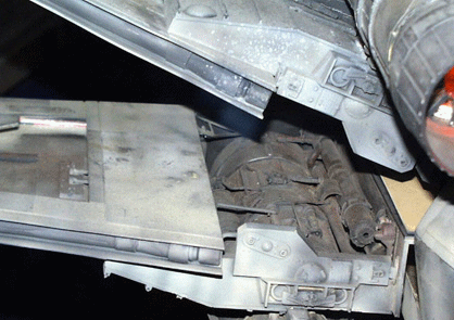
NOTE: Save your files frequently. That way, should anything go wrong, you don't have to go back very far to restart your project.


1. This should be an 'old hat' to you by now. Adding a few bumps to the engine housing. Follow the bevel suggestions, then go to Point Edit, grab some end points and slide them as desired. Then bevel again.


2. To sculpt the engine a little more, since the outside skin is not present in this place, do a 'Shift-f' smooth shift, place the cursor in the center of the circle and pull in a little.


3. Make a disk, then make some more, and some more and... ok..when you're done with this line them up and then bevel away, This is adding stuff to the space engine.


4. I suddenly remembered the Bridge Tool. Great stuff. Select two opposing polygons and hit Bridge, and a polygon bridge is automatically created. You can see that I am using that in several instances, including the cross-over. Here I am doing a bit of point editing to curve the bridge a little bit.


For additional detail, copy this set of pipes, a little slenderer maybe, to the aft part of the space engine. Not the one with the cross-over. That only goes to the front part.


Making the two cross-over parts out of tubes, or just making them thinner, will be just a little bit more challenging, but enhances the "authentic" look.


5. Now for some tubes or wire bundles that run around the thickest part of the space engine. To make that form-fitting, I am COPYING the highlighted polygons from the engine part around which the bundles are to run. In an empty layer, collapse them to a single line. Then select the polygons (now just a line) and hit 'k'. That will 'kill' the polygons, but keeps the points around. It's the points we're after. I used Shift-h to just slightly expand the diameter of the half-circle of points, to allow some space for the actual tube/bundle diameter.


Select the points SEQUENTIALLY and make an Open Curve. Again, the diamond shape tell you the start of the curve. After that, in sideview, go and add a little shape to the curve by moving a couple of points laterally.


Now place your disk ( the size of the disk, will affect the look, and is up to you. I think thinner is better, but not too thin, or the fine detail won't be very noticable) in the exact center of the the starting point and do a Rail Extrude.


For practical reasons, make a couple of cylinders to terminate the bundles, and copy the whole thing twice. Looks pretty neat, what?

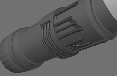
Select all of those cool polys you just created, hit 'q', and name them 'engine_pipes 1', o have some texture control over them later.

6. Ok, getting close to the end here. How about those wing locks. Not too difficult. Create a box and make sure it has four segments in the X-axis.


Take the top center polygon and bevel it, then, as you can see here,do the sides, fronts, and so on. Just bevel the same way and you will get some decent looking locks (or maybe call them wing guides. Whatever). After you are all finished, you can add any level of detail (nurnies) as you can get from the reference photo at the top of the page.
Oops! Correction! Make that a Shift = 0 mm and Inset = 40 mm in the left image.


9. The wing tips have this little extension. An easy couple of bevels and then some points editing top down, to get it to look nice and smooth.


10. To get the wing cut-outs, you will have to slice into the wing. This is not a CAD exercise, so 'eyeball' it and know that 'close, is close enough'.


11. Because of one of them being rather oddly shaped, a little trickery is on order, followed by some point editing to get the angle set up. Make sure you delete the extra (two) polygons in the middle of the second wing cut-out.

You can clearly see here, that we are not too far off from the 'real' thing.


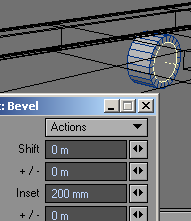


12. Now for the gun(s). You see bevel instructions, where you can bevel. If there are no bevel instructions, you can bevel anyway or use 'e' and extend the polygon to a given distance using Set Value.


For the cooling fins, simply pick every other polygon and then bevel them according to instructions shown.

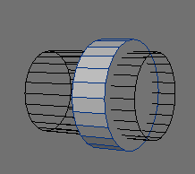


Now for the gun cooling fin shroud. Just create a cylinder, a little larger than the gun's diameter, and copy it to an empty layer, shrink it, stretch it, and use the Boolean tool to subtract the center.
In the downloaded file you will see that I named the gun shroud and gun surfaces, and I suggest that you do that. Both of them may be colored differently from the rest of the equipment. Also, there are some additional gun details that you can get from the website of the people that restored the small 3/4 scale X-Wing. Excellent details. Go there: X-Wing Restoration.


13. The beam deflector: I ended up copying the gun shroud for this and turning it 90 degrees, cutting it into half. Leave it in the separate layer. You'll put it into its correct place later.


14. Meanwhile, continue with the gun beveling.
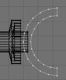

15. Now it's time to slide the deflector in place and PASTE it to the gun layer... Next do the final little rod and you're done. Additional detail is entirely up to you.

16. It happened that my two little boxes I used as supports for the gun still had the four sectors in the X-axis, so I kept that and put it to use. It makes them a little more streamlined.


17. I simply could not let you go without a guide for the torpedo launcher tube. Here is how I did it. There has go to be a better way, but this works. Create some points in this shape, and then, after mirroring them down (Y=axis), sliding them close together, select them sequentially and hit 'p'. The polygon you just created will be used to stencil the shape onto the side of the lower fuselage. Make sure that the shape has a name, (I called mine: Launcher) and then slide it outside of the fuslage in an empty layer. If you ever do my stencil tutorial, then you will know why you want to keep it outside of the surface onto which you want to stencil.
Now stencil that baby.

18. Next, you can bevel or extrude it slightly, but the Inset is tricky, because the launcher is coming to a near point. Clean it up with Point Editing. The points will probably cross over each other. Use maximum magnification to straighten them out.

19. Next, slice it all up, where the points are.

20. Then make a horizontal cut, and then start point editing to give it some depth into the fuselage. The horizontal cut allows you to dish the shape in a little more.

21. There is a darker side panel around, on the lower fuselage. Simply bevel it into existence.

22. A long horizontal cut will give you the areas to color red (or green - I guess, depending on squadrons, it may be different colors).

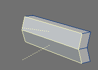
23. Lastly, to the place where the wings are anchored. Just copy the ledge that you created earlier for the wings from both upper and lower fuselage and combine them in an empty layer. Close the front with a couple of polygons.

24. Now bevel those polygons.

25. After that is done, you will need to reconcile the points in the front/back view and sideview.


26. Next, using Set Value again, but this time move the selected points to 6.5 m.
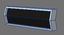
27. This is what you are shooting for. Go ahead and name and color the center area of the wing achor.


28. Just so you know, this is what I used to build the image at the top. However, the file below, has the all of the parts and all you need to do is mirror them as needed. Everything is in there, including the droid. The pilot and interior are, as you already know, here: Xwing4.ZIP. For your convenience, I named the gun and gun cooling shroud as separate surfaces (notice, the color of the shroud in this picture).
I realize that I could have just given you the whole model (as I so often do on my Downloads page), but then I should not have bothered with the tutorial. This way, should you actually do this tutorial, you will have the skills to easily complete all of the fine details. If you just download the files, then you missed out on the learning experience and still will have to finish it on your own. Makes me feel better :-), especially in view that I have never ever received credit for any of my models being used by anyone, other than professionals. Hobbyists just scavenge and run for the hills and then forget everything else. Pros act like, well, professionals.


Two of the best resource photos for the topside of the fighter, with excruciating details, that are simple but tedious to create and would have taken up a whole other part of this tutorial, and easily over a hundred detailed images. Too much for me, and not enough creative freedom for you. Just take your time and do it a little bit at a time.

My own X-Wing's detail is not nearly as gnarly as the stuff on these movie props, but they sure are great guidelines. This picture shows you the relatively low level of detail that I put on the top of the X-Wing. However, from the distance and at oblique angles, it gives me the desired nurnie-clutter that I want.

One more thing: In case you are wondering about those lines that are bumped into the fuselage, it's just adding one of the popular Hull textures, that are downloadable from the web, to the bump channel of the fuselage. Simple as that. You can copy it here, or you can go to Photoshop or PaintShop Pro, or use any drawing utility and draw a few squares and rectangles, as you see here, and put that pic into the bump channel. The result is the same.
NOTE: For a larger bump surface (such as the fuselage, maybe), you can also combine both the cockpit bump and this one into a larger image.
Alrighty then, the rest is up to you. You can nurnie and texture to any level of desired detail. You already know from my own model where I said, "enough is enough". It all depends on what you want to do with the model. That will ultimately satisfy the level of texturing and detail that you desire. On my webpages and in here, I provide all of the needed references or access to them.
I hope you enjoyed this long journey and produce some models that are not all cookie-cutter identical, but show some individual modifications, even within the limitations of the Star Wars universe. Best of luck and remember, it's supposed to be fun.
You can download the complete mesh, as you see it in the picture, above (last update 27 AUG 06): Xwing6.ZIP
Created by Karl Stocker (pixeltek), a 3D hobbyist and occasional freelance artist. If you'd like to contact him, send email to: pixeltek@yahoo.com or visit his website at: www.cosmic-pearl.com