Part 5
Here we go for the fifth installment and the cockpit interior.
NOTE: Save your files frequently. That way, should anything go wrong, you don't have to go back very far to restart your project.
1. Go into the layer with the upper fuselage and cut this polygon.
2. Select these two polygons and hit 'e', and then snap them to the indicated Set Value Y-axis location. We'll fiddle around with that a little bit more later.

3. Done!
4. Now delete the extension artifacts.
5. All of them!

6. I said, "All of them!" Just to point out, since polygons are normally one-sided, sometimes we don't see the extra ones until we spin the model around or click to highlight all polygons.

7. Now select all of the cockpit floor polygons and drop them to this value.
8. Make sure all of them are part of the move.
9. Which, if correctly done, will leave us with a little horizontal gap. Not a problem. Just grab the two points at the boundary, hit 'e', and let Set Value snap them to the centerline and ...

10. ...voilà. Gap eliminated.
11. Trying to fit some stuff, I actually dropped the back part, where the pilot sits, to this value. Which produces a sloping floor, under his feet.
12. You can see the here. Next, to differentiate the interior walls from the X-Wing's skin, select them, name them, and give them a different color.
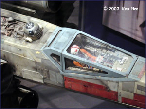
NOTE: In the reference picture at the top of this page, there is an actual model, custom made by someone talented. When you are finished modeling, I suggest that you use that photo as your cockpit color scheme reference, unless you have discovered a better resource. So the final colors will be entirely up to you.
1

3. This happens to be what I used for the cockpit walls.
14. Next, put some equipment into the cockpit. Make a box.

15. None of this is very critical. Just make it look good. You seee how I aligned the outside edge of the side console to the cockpit wall.

16. Make a second box. I prefer to do this in an empty layer. Note that the box has an X-axis segment of 2.
17. From the side, you need to ramp the top of the dash up, but leave some room for forward visibility.


18. A little bit of point editing.
19. The dash modile, too, needs to slope down, as seen from the front (or back).

20. Once that is complete, select the two polys and bevel them in.
21. Then bevel them back.

22. Make sure that all of those points shown here are moved onto the centerline. Next select the centerline polygons and delete them.
23. Now to make the dash one uninterupted surface. Weld the points shown (right to left). Then turn the model to get to the backside points and weld them (left to right).
24. Following that, delete the leftover polys.
25. In the X-axis, you can make them even this way. I find Set Value an invaluable tool for all kinds of things.

26. Here's how it looks (well half of it anyway).
27. Let's stick a sample piece of equipment into this cockpit - a small view screen.

28. A quick bevel to shrink the screen, and ...
29. Color it green with luminouscence. Color it any color you like and make it shine.
30. Looking in from the outside. Looks cool from here, but if you want the authentic look, go to the pic at the top of the page.
31. The guy, my old standby LW low-res pilot figure (Luke), helmet, and seat are my freebies to you.

32. Rendered, the interior looks like this. I wrapped the Dash.jpg (below) around the consoles with a mild bump and it looks not bad at all. This is what's included in the latest version of the interior file download, at the bottom of this page.
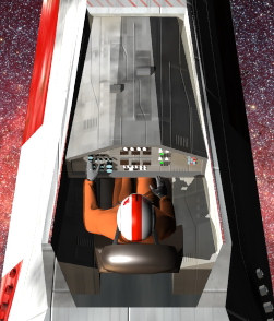

33. What I did. I wrapped a hull texture, similar to Dash.jpg around the consoles, then added a couple of small boxes or cylinders for surface detail, and dirtied it up some. BTW, you are aware that you can reuse texture layers, i. e. copy them, and paste them into any other surface textures, right? It makes texturing work that much easier. Or you can "roll your own". Use Photoshop or PaintShop Pro, or any drawing utility, and draw a few squares and rectangles and put that into the bump channel.
NOTE: Small primitives on top of the instrument panel, such as cubes and cylinders serve as levers or buttons.
How to apply the texture: cubic, automatic sizing, and repeat that in the bump channel. You can experiment with that for different effects and with modified textures.
You can download the cockpit interior mesh here (last update 27 AUG 06): Xwing4.ZIP
In part 6 of this tutorial you will create the Wings and Engines.
Created by Karl Stocker (pixeltek), a 3D hobbyist and occasional freelance artist. If you'd like to contact him, send email to: pixeltek@yahoo.com or visit his website at: www.cosmic-pearl.com