Adding Detail to a Spaceship's Hull with the LW Stencil Tool
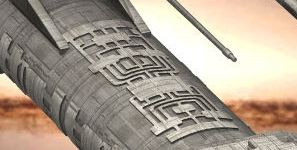
Recently, a friend of mine dazzled me with pictures of which I show some details below, and which can be seen in its entirety by clicking on the detail image below:
Figuring that what can be done in Solid Works can be done in LW as well, I decided to set about using the pen and stencil tools to attempt to get a similar result.
Method One:
1. Open LW modeler, click on the Pen tool available in the CREATE tab and draw this outline.

2. Selected the points along the center line (all two of then, in this case) and hit Ctr - v or DETAIL/ Set Value, to align them to an common X value. Zero, for this image.

3. Under MULTIPLY/Mirror mirror the polygon on the X-axis.

Create an arbitrary oval "hull" shape, or use these specs. You can choose any shape you want for this.

4. You must consider the direction in which the stencil is supposed to project the image. A little like a movie projector projects an image onto the movie screen. In this case we want the image on the top of the hull. If you wanted it on the side, you would rotate the stencil 90 degrees and move it so that the image would project along the X -axis. In this case it will project down, along the Y-axis. Also, it is important to keep the stencil polygon away from the object onto which it will be projected. Notice that the hull object in the background layer is not touched by any part of the stencil polygon.

5. Got to the DISPLAY/Swap layers tool or hit the apostrophe key and place the stencil in the background layer. Then go to MULTIPLY/Drill and in the Template Drill window select your projection axis. The Y-axis is used here.

6. Hit "ok" and the result will be a projected image onto the hull shape. One at the top, and one at the bottom. To avoid the bottom image, you can simply cut the hull polygons below and save them to another layer and return them after the stencil process is completed. In this case I wanted to see how they'd look on both sides.

7. After this, select all of the polygons that are now stenciled on the hull object surface, and then deselect all that are not part of the stencil image:
8. Go to Shift E, or to MULTIPLY/ Extrude and depress the Ctrl key while moving the polygons in the direction of choice. You noticed that I had both, the top and bottom stencil image polygons selected. I wanted to see how this worked both extruded out and in.

9. Next, select all of the extruded polygons and hit the "f"key to flip them. The extrusion process seems to invariably flip the normals and render the polygons kind of invisible as you can see in the previous illustration. Once flipped, with the polygons still selected, hit the "q" key, and in the Change Surface dialogue window, name them. I named them "hull etch" and assigned a color. You don't have to choose a color at this time, because once the surface it named, it is present in the Surface Editor and can be colored and textured there at any time.

10. Here is the un-rendered result; a positively and negatively extruded (intruded?) surface feature.


While this works adequately, I wanted to get more intricate detail and decided to try another approach.
Method Two:
This time, I wanted something more like what is shown in my friend's image. I considered the Pen tool as too awkward to use and decided to just create a bunch of flat boxes and disks, and for the curved paths decided on rail extrude. Some of the tools' descriptions provided in Method One will not be repeated here, though most of the same tools will be used in Method Two as well.
1. Open LW modeler and create a few points under the CREATE/points tool selection and under Make Curve select the Open Curve option to connect the dots.

2. Next, in a different layer create a little rectagle. Switching Layer (you know, the apostrophy key), select the curve and make sure that the little diamond, that indicates the start of the curve, is at the end where the rectangle is located.

3. Switching layers once more, and it's off to the MULTIPLY/Rail Extrude tool. In the little dialog box click ok, and let her rip.
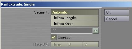
4. The result was as expected. Something that looked like a Radar wave-guide on an airplane.

5. Going to the POINTS edit mode, select all of the points on one of the surfaces and hit the "X" key to delete them.

6. Now you're left with a 2D object, that will require some cleaning up. Use the previously mentioned Detail/Set Value tool to align the edges and the MODIFY/Drag tool to unsnarl the inside corner points. The extent of the cleanup is completely up to you. Keep in mind the reduction in size of the final object, as it will appear in a render, to temper your efforts to an appropriate level.


7. Enough of all of this and on to the stencil object. By mirroring this curved
item and repeating it, flipping it around, adding disks, and rectangles, you
may end up with one or more stencil objects. In each case use the DETAIL/Set
Value tool and select all of the points in the point edit mode to bring all
of the various 2D parts to the same plane. Your imagination, needs, and creativity
are your only limitations here.


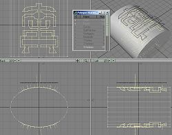
8. Reusing the same old "hull" object from Method One, place the stencil objects in the axes where you plan to project them onto the hull shape.

9. Next the stenciling process: first on one axis, then in the other, using MULTIPLY/Drill/Stencil with the correct axes selected and the stencil shape in the background layer. However, following a suggestion by William Vaughan, I ended up duplicating the hull shape a couple of times (once for each stencil). The reason is that prior to extrusion all of the polygons not belonging to the stenciled image will be deleted, i.e. the hull object will bedestroyed. The illustration shows the set-up for stenciling along the X-axis.

10. Now to the deletion of all that is not part of the stenciled image. This is a task best performed in the single viewport mode, that can be easily entered by placing the cursor in the viewport to be enlarged, and subsequently hitting the zero key on the numeric keypad, with Num Lock enabled. Also, whenever you suddenly notice strange things happen when you hit the keyboard shortcuts, make sure the Caps Lock has not been accidentally engaged. Here's the result of our labor - part one - two curved, yet still 2D, objects that have the exact curvature of the hull.

11. This will be repeated for any other object that you intend to stencil. Next, if you want them both extruded, select them one at a time and extrude each for the desired amount in the opposite direction. Tip: After you exit the first extrusion process hit the "f" key, with the extruded polygons still selected, to flip them. Next go to DISPLAY/Sel Inverse and repeat the entire process on the currently selected object. Another Tip: After activating the Extrusion tool, open the numerical window (hit the "n" key) and the new extrusion will have the exact same displacement as the previous one and in the correct direction. Looks like there might be some neat other possible uses for this kind of output, such as complex screens, columns, exotic futuristic gear, and much more, with and without an inner solid shape.

12. Repeating the whole process for the next stencil shape long the Y-axis yields this result. "Full house!" There now are four extruded and conformal shapes.

13. After a little bit of texturing, the final result should look similar to this.

The Method Two file with most of the bits and pieces can be downloaded here: Stencils.zip
Created by Karl Stocker (pixeltek), a 3D hobbyist and occasional freelance artist. If you'd like to contact him, send email to: pixeltek@yahoo.com or visit his website at: www.cosmic-pearl.com