
Splines are fine for the Gokstad Viking ship
1. Maximize the perspective view (you know, place the cursor into the view port you want to maximize and click on the <0> key in your numeric keypad, Num Lock on) and rotate the image as shown. Switch to the polygon edit mode and select the polygons in the order I show you: top, bottom, left, right. The order will be helpful, but is not essential. You may experiment.


2. Click <Ctrl-f> and enter in the Make Spline Patch
window the numbers as indicated. Hit "ok" or <Enter>.
This is what you get:


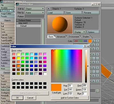
3. You say, "Wait! I did not! Where's that color come from?" Ok, here's how: Go to the Surface Editor, select Default, and click on the little color square to bring the palette up. There click on any color you like, as long as it looks like mine :-). No really, it's your choice. Make sure you check "Smoothing" in the Basic tab page.
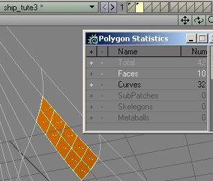
4. Ok, with that out of the way, we need to do something with that patch. Hit <w> and the Polygon Statistics window will appear.
a) click on the Minus sign next to Total (fig 2-8)
b) click on the Plus sign next to Faces (fig 2-9) (if you followed my suggested selection order you'll have polygons facing you - if not, click the <f> key to flip them)
c) select a new layer (click on the lower half of another layer field)
d) click the <x> key (polys will disappear) (fig 2-10)
e) click the <'> key to switch layers (spline cage appears as black outline)
f) click on the <v> key and polys will reappear (fig 2-11)
g) click on <'> again to return to the original layer and select the polygons for the next patch as in figure 1. Do this until all patches have been created.


5. NOTE: Occasionally you will get a message
that "The Curves Don't Cross Correctly". What happened will be that
you have selected an additional polygon line, as I did, in this case (see weird
arrow). Other possibilities could be that there are more than one point involved
at one intersection. However, in this particular case, I hit "ok"
and simply deselected the extra little polygon line and all was fine.

6. Are you finished? That wasn't that bad now, was it? Save your file as ship_tute4.lwo

7. . Now it's time to patch the keel. You know the drill. In the perpendicular
view in the layer with the keel, select the polygon lines (in this view) L,
R, Bottom, Top. You have to enlarge the picture a lot to see them clearly, near
the tip. I suggest that for the thin edge of the keel 1x5 polygons will be fine.
On the side use the same as we did before, 2x5. With faces selected here is
what you'll have. Cut and paste the patch to a new layer. Continue until all
three sides of the keel are finished. For practical reasons, it will be easier
to finish the top and bottom edges first, then reset the numbers and do the
wider outside edge. Don't forget to flip the faces where necessary. The little
top area you can just close off the old fashioned way. Select the corner points
sequentially and hit<p> to create the polygon. Make sure
it's pointing up, or flip it. Copy it to the mesh layer as well.


8. BTW: To tell you what may happen. While transferring a patch, I accidentally
cut some of the lines to the patch layer. It happens. When I returned the lines
to the spline cage and attempted to patch the next section it gave me the dreaded
"The curves don't cross correctly" message. I figured it had to be
points and went to the point edit screen and hit <m>
and did an automatic point merge. 16 points were eliminated and that fixed my
problem.
Once the narrow edges are finished, start on the wider, outside edge. Continue as previously discussed.

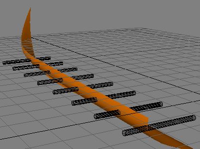
9. When all done, this is what you'll have. Save your file as ship_tute4.lwo
(click "ok" about the overwrite)

10. Let's do a little test render, and I must say, I am not displeased. We're
right on track.

11. I will give the oarholes one more try. The last attempt did not come out particularly well. There were huge stress lines in all of the affected panels and I am still asking questions about what we can do about that or if we want to live with that. I will provide both ship panels as options as well as the Boolean objects. In the end you can make up your mind which version you want to pursue. So, in the meantime, just copy the Boolean objects from the attached file to your practice file and perform the Boolean operation as I describe it.
With the Boolean objects in place, create a copy of your hull in a new layer.
12. With the hull in the active layer and the Boolean objects in the background layer, go to MULTIPLY/Booleans or <Shift-b>, and the Boolean CSG window will open. Select "Subtract" and hit ok.

13. Here's what you'll have. A perforated hull segment, artifacts and all. Apparently this is a tough one for the software. Not to worry...

14. Simply, in the polygon edit mode, select all of the offensive polygons, (best done in the lower-right viewport - head-on view) and make sure you get the circilar end polygons too. Like this, and then hit <x>, and they'll be banished into cyberspace - unless you hit the <u> key. Then you can get them back, should your dark little heart desire that.

15. At last, here is the hull segment, oar holes, stress areas and all. Save your file as ship_tute6.lwo What happened to file 5? I used it as the before Boolean and file 6 as the after Boolean operation. Anyway, the Boolean object is in layer six of the zip file. Have fun. Render the result and see what you think. Maybe it's nothing, but at this time I am not pleased. Hang tight, however, in Part 3 we'll take care of this.

You can download the .LWO file here: Viking2.zip
In part 3 and part 4 of this tutorial you will create the complete hull, deck, mast, mast-fish, and other smaller details of this sleek vessel.
Created by Karl Stocker (pixeltek), a 3D hobbyist and occasional freelance artist. If you'd like to contact him, send email to: pixeltek@yahoo.com or visit his website at: www.cosmic-pearl.com