
This is what you are aspiring to do, if you have minimal LW skills, such as myself.
Let me biefly preface what I am offering to guide you through. There will be some "hand-holding" in parts, but I expect that you have some reasonable amount of LW knowledge. This model is done in LW 8 & 8.5. I can only address that, although I think you can do this with previous versions just as well. I will not take you into all of the "nurnie" details. It would require endless pictures and bevel instructions, and you can do what I did, gauge it visually and have "fun" the old-fashioned way - work for it. I will provide the pilot, the same one I used in the T-16 model. He's supposed to be the same guy anyway, right? Texturing: I used only procedurals and I believe that they are part of any file anyway. Anything over and above is up to your own desirement, research, and skill level. Many of you will exceed me easily. Lastly, please don't contact me, unless you discover a real error here. This is not a design-engineering CAD exercise, we're just trying to get close to an imaginary model. Close enough that any difference makes no difference. Nothing here is real, keep that in mind. We are playing with someone else's imaginary product.
Will you discover easier and better ways to do some of the things? Many of you certainly are. Good for you. As in all things 3D, there are usually more ways than one to arrive at a successful illusion. I demonstrate just my own.
NOTE: Save your files frequently. That way, should anything go wrong, you don't have to go back very far to restart your project.

1. Open LW. Use 1m grid. Hit Space and then create the following box.
NOTE:
This
box should be in Layer one by itself. It is used to show the backdrop images.
The background images can be downloaded from here:
Xviews.ZIP


2. To project the views into the background of your work area, hit 'd' and select the backdrop tab. Then use the following Display Options images to set you up. The arrows show you which viewport we are dealing with, which image is used, and the adjustments to be made. Notice, the adjustments are in millimeters, not meters. You will still find small differences in the image sizes, and since that is just taken from some other model, I am extrapolating between. You'll see what I mean later.

3. Next go to layer two (2) and create this box according to the data shown (NOTE: the axis used is 'Y').

4. The nosecone is made in two parts, so the box shown is the upper portion only. You also notice the backdrop image here, and the slight discrepancies between them. My own excuse is always this, having been around fighter airplanes for decades: equipment, such as is used in Star Wars, is often decades old, and manufactured on different planets at that. Chances are that there are tons of local modifications made when old equipment is being refitted and overhauled at different times and in different parts of the Star Wars universe, all depending on resources and improvements and technologies that are on hand at the time.

5. Now go and subdivide the box twice.


6.
Select the back polygons (closest to the 'Y'=0 axis) and delete
them.


7. I find it convenient to work with just half an object, if it is symmetrycal. So, if you want to, delete the points shown and then hit the Space Bar, and in the polygon mode go to the statistics panel, find 1- and 2-vertex polygons and delete them. Keep looking for those things and clean them up.

8. In the top view, locate the edge of the sensor panel indentation and make a cut ('Shift-k') along that edge, as shown.

9. Now for some tedium (much more to come, heheh): Point Editing - it is time to adjust the shape of the subdivided box to that of the background image. First in the side view, and then in the top view, and any other way you can think of.


10. Here is where that gets us, and by hitting 'Tab', you can evaluate the progress you are making. Toggle back and forth between adjustments, until you are satisfied with your progress.


11. Another little cut at the bottom gives the nose cone a bit more of a rounded edge. Note the point-edited adjustments on that lower edge.


12. Here is where we want to be, but wait, there is a little more...let's make one more vertical cut.

13. Select the polygons (in the stats panel), then hit 'q', and name the surface 'nosecone'. You can smooth it and give it a color. I did at the time, but later changed it to the same color as the fuselage. You'll see why in upcoming reference pics.

14. "Aha!", you say, "so far so good, but what about the lower half?"
Well, in the side view, we'll just mirror the top half, that is, in the Y-axis. Do it exactly as you see it here.

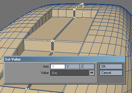
15. You already know that the back edge of the lower half of the nosecone is flat. To make that happen, select the points, as shown, and hit 'v' to get the Set Value window open. For the Z- axis enter the shown value and hit OK.

16. Next, delete the highlighted polygons between the two halves.

17. Time for a little Bandsaw action. Select the polygons you see here, and cut and paste them to an empty layer. Open Bandsaw, and cut them down the center, then cut and paste them back to the nosecone layer.


18. You will notice a small open area. Sect the four points you see here, and hit 'p' to form a polygon. Then select the three points around the remaining tringular opening and hit 'p' again. If you have any problem at this point, make sure you select the points SEQUENTIALLY. If the polygon seems wrong, hit ' f ' to flip it. If it still doesn't act right, hit 'm' and do a fixed Point Merge. Sometimes that straightens things out. You may also want to go to the DETAILS tab and under 'more' find the Unify Polys function and make sure there are no duplicates hiding there or anywhere. Consider those occasional checks, same as looking for one- or two-vertex polygons. It's all part of your good mesh maintenance.

19. Now for a major bit of point editing. Select the points you see here, then hit 'h', and place the square-looking cursor on the centerline and pull the points up (best while holding the Ctrl key). That will give you a pretty good head start. Then fine-tune it with additional point editing.


20. Once you are satisfied with the shape of the bottom half of the nosecone (save your work) and select all of the points at the back edge and hit 'e' (extender) and then hit 'Shift-h' and pull inward. All of the points should move toward the center. Now do it again. A little clean-up will be necessary here, because the scaling-down also caused a slight horizontal shift. So make sure that the first set of polygons is perpendicular to the skin surface, but the second extension can stay folded-in (as shown in the bottom image).

21. Ok, time to "freeze" this puppy. Go to the 'CONSTRUCT' tab and then find 'Freeze' in the tool choices, bottom-left, and this is what you'll see.


22. Having done that, grab these polygons, (I let the background image be the guide here) and one-by-one merge them ('Shift-z'). Afterward, select the now extra points and get rid of them.


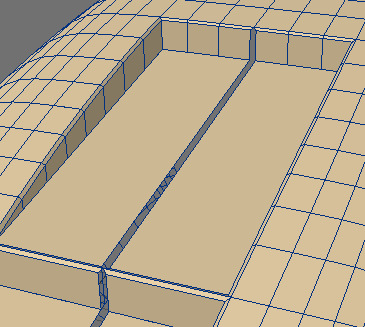
23. Next, I did this. I merged the polygons into two retangles, then beveled them slightly down, as shown. Next, move the two polygons to anther layer.
BTW, don't forget to save your file frequently! That way, should anything go wrong, you don't have to go back very far to restart your project.

24. Next, take the still selected area, after you completed the bevel and deselected the bevel tool, and hit 'e' and pull the polygons vertically down. Then deleted the new polys created along the centerline. They are not needed.


25. Now merge the polygons horizontally, and remember to delete the extra leftover points.

26. From reference pictures you know that a step is needed here, so grab the two points shown and lift the whole polygon up.

27. This is the look we're after.

28. Select both layers and make sure everything is where it should be.

29. You may see something like this. No problem. All you do is select all of the points along the centerline, hit 'v' and in the Set Value window enter a zero for the X-axis and hit OK.


30. All done. The nosecone is satisfactorily similar to the one in the background images. Save the file.

31. This sceen grab shows you what you should have at this point, after mirroring and selecting both layers.
(last update 27 AUG 06)
You can download the nosecone mesh here: Xwing1.ZIP
In part 2 of this tutorial you will create the upper fuselage.
Created by Karl Stocker (pixeltek), a 3D hobbyist and occasional freelance artist. If you'd like to contact him, send email to: pixeltek@yahoo.com or visit his website at: www.cosmic-pearl.com